Wavemeter based on interferometer: Difference between revisions
| (74 intermediate revisions by 2 users not shown) | |||
| Line 9: | Line 9: | ||
Michelson interferometer is a good tool to measure the length if there is a good laser. Similarly, it can also be used to measure the unknown wavelength of a laser by calculating the ratio of wavelengths between the unknown and a known laser. Here we use a 1550nm laser as our reference. By counting zeros in the signal, we can get the ratio between wavelengths. | Michelson interferometer is a good tool to measure the length if there is a good laser. Similarly, it can also be used to measure the unknown wavelength of a laser by calculating the ratio of wavelengths between the unknown and a known laser. Here we use a 1550nm laser as our reference. By counting zeros in the signal, we can get the ratio between wavelengths. | ||
In Michelson interferometer, an input beam is splitted into two and reflected back by their respective mirror. The two beams with a phase difference caused by travelling different optical path lengths would form an interference pattern after overlapping. If we change the optical path length difference of the two beams, i.e. change the length of one arm by moving the mirror, the interference pattern would change simultaneously. | [[File:Optical_setup.jpg|500px|thumb|Optical setup of wavemeter]] | ||
In Michelson interferometer<ref>https://en.wikipedia.org/wiki/Michelson_interferometer</ref>, an input beam is splitted into two and reflected back by their respective mirror. The two beams with a phase difference caused by travelling different optical path lengths would form an interference pattern after overlapping. If we change the optical path length difference of the two beams, i.e. change the length of one arm by moving the mirror, the interference pattern would change simultaneously. | |||
Consider the planar wave case, the two reflected beams could be written as <math>E_1=\frac{A_0}{2} e^{i(\omega t+knx_0)}</math> and <math>E_2=\frac{A_0}{2} e^{i(\omega t+knx_0-2knx(t))}</math>, where <math>A_0</math> is the amplitude of the input beam, <math>\omega</math> is the angular frequency, <math>k</math> is the wavenumber, <math>n</math> is the refractive index of air, <math>x_0</math> is the length of one constant arm and <math>x(t)</math> is the length difference changing with time of the other arm. | Consider the planar wave case, the two reflected beams could be written as <math>E_1=\frac{A_0}{2} e^{i(\omega t+knx_0)}</math> and <math>E_2=\frac{A_0}{2} e^{i(\omega t+knx_0-2knx(t))}</math>, where <math>A_0</math> is the amplitude of the input beam, <math>\omega</math> is the angular frequency, <math>k</math> is the wavenumber, <math>n</math> is the refractive index of air, <math>x_0</math> is the length of one constant arm and <math>x(t)</math> is the length difference changing with time of the other arm. | ||
| Line 28: | Line 29: | ||
[[File:pic1.jpg|500px|thumb|Wavemeter setup]] | [[File:pic1.jpg|500px|thumb|Wavemeter setup]] | ||
===Optics=== | ===Optics=== | ||
List of all the optic components used: | ;List of all the optic components used: | ||
Silver mirror x6 (to adapt broadband laser that might be measured) | :Silver mirror x6 (to adapt broadband laser that might be measured) | ||
BB1-E04 mirror x2 (for 1550nm reference laser) | :BB1-E04 mirror x2 (for 1550nm reference laser) | ||
50/50 Beamsplitter 1100nm-1600nm x1 | :50/50 Beamsplitter 1100nm-1600nm x1 | ||
C220-c Aspherical lens x2 (for fiber input of two lasers) | :C220-c Aspherical lens x2 (for fiber input of two lasers) | ||
TS975M-M01B Retroreflector x2 | :TS975M-M01B Retroreflector x2 | ||
f50mm lens x1 (for unknown-laser detector) | :f50mm lens x1 (for unknown-laser detector) | ||
f35mm lens x1 (for 1550nm detector) | :f35mm lens x1 (for 1550nm detector) | ||
PDA10CS-EC detector x1 | :PDA10CS-EC detector x1 | ||
PDA50B-EC detector x1 | :PDA50B-EC detector x1 | ||
===Air track=== | ===Air track=== | ||
The whole setup including air track and optics is built on a 750mmx750mm breadboard table. The aluminum linear stage is 550mmx50mm with a 150mmx50mm sledge sliding on its V-shape surface. The friction is reduced by producing an air cushion between the two surfaces using 10 small holes on the bottom of sledge that is provided with compressed air via a silicon tube. Two springs are attached to both ends of the sledge and fixed around two long screws. Besides the force provided by springs when reflected from ends, the kinetic energy loss is also compensated by a small push pull solenoid fixed on one end of the stage. Two optical switches are mounted on board to detect the signal when sledge reaches ends by a piece of paper fixed on sledge, controlling the solenoid. | The whole setup including air track and optics is built on a 750mmx750mm breadboard table. The aluminum linear stage is 550mmx50mm with a 150mmx50mm sledge sliding on its V-shape surface. The friction is reduced by producing an air cushion between the two surfaces using 10 small holes on the bottom of sledge that is provided with compressed air via a silicon tube. Two springs are attached to both ends of the sledge and fixed around two long screws. Besides the force provided by springs when reflected from ends, the kinetic energy loss is also compensated by a small push pull solenoid fixed on one end of the stage. Two optical switches are mounted on board to detect the signal when sledge reaches ends by a piece of paper fixed on sledge, controlling the solenoid. | ||
=== | ===Signal Process=== | ||
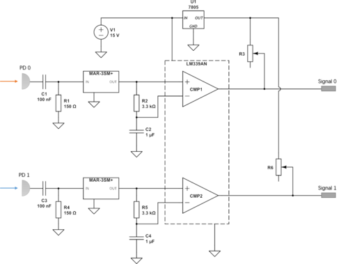
The | The circuit for processing signal. The signals generated by photodetectors are small and dc biased. To enable our counter, we need to transfer the signal to a 0-5V signal. We first use a high pass filter to get rid of the dc part. Then a monolithic amplifier is used to amplify the ac signal before we put it into our comparator. The comparator is used to generate the 5V signal. The output port of LM339AN can be seen as a transistor so use a pullup resistor connected to 5V we can accomplish it. | ||
<gallery widths=500px heights=400px> | |||
File:Signal circuit.png|800px|thumb|signal processing circuit | |||
</gallery> | |||
'''Comment''': Congratulation, obviously it worked ;) However, the MAR amplifiers would need a resistor at the positive supply feeding in DC current for them to actually amplify the signal. Maybe you did not need it in the case here... Also, keep in mind these amplifiers are internally terminated with 50 Ohm to ground: The additional resistors with 150 Ohm at their input only lowers the total input impedance to 1/(1/50+1/150)=37.5Ohm, so you likely have a higher cutoff frequency than what you thought. But hey, it worked! | |||
2 Resistors for | ;Components we use: | ||
[[File:Signal board.jpg|200px|right|thumb|board for this circuit]] | |||
:2 Resistors for high pass filter <math>150\Omega</math> | |||
:2 Capacitors for high pass filter <math>0.1\mu F</math> | |||
:2 Resistors for low pass filter <math>3.3k\Omega</math> | |||
:2 Capacitors for low pass filter <math>1\mu F</math> | |||
:1 Quad Differential Comparators LM339AN | |||
:2 Monolithic Amplifiers MAR-3SM+ | |||
:1 Voltage Regulator L7805SCV | |||
:2 Potentiometer | |||
===Control Circuit=== | |||
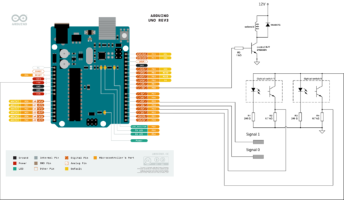
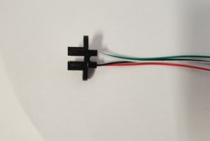
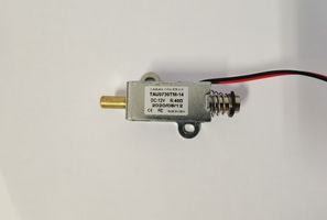
The schematic of the circuit for control is shown below. Arduino UNO<ref>https://store.arduino.cc/usa/arduino-uno-rev3</ref> board is used to control and count signals and should be connected to a computer to power it and get reading. Two optical switches are used to get rid of signal change when car gets pushed back. The optical switch 0 is also used to turn on/off solenoid. A push pull solenoid is used to push the car and compensate for energy loss in motion. | |||
<gallery widths=500px heights=400px> | |||
File:wavemeter circuit.png|thumb|right|800px|control circuit | |||
</gallery> | |||
;Components we use: | |||
:2 Optical switches OPB881T55Z | |||
:1 Push-Pull solenoid TAU0730TM-14 | |||
:2 Optical detectors PDA10CS-EC and PDA50B-EC | |||
:2 Resistors for photodiode <math>240\Omega</math> | |||
:2 Resistors for phototransistor <math>6.7k\Omega</math> | |||
:1 Resistor for transistor base <math>1k\Omega</math> | |||
:1 Transistor 2N2222A | |||
:1 diode to protect 1N4007G | |||
<gallery widths=300px heights=200px> | |||
File:wavemeter_optical_switch.jpg|thumb|300px|optical switch | |||
File:wavemeter_solenoid.jpg|thumb|300px|push pull solenoid | |||
</gallery> | |||
==Program== | ==Program== | ||
| Line 82: | Line 109: | ||
[[File:wavemeter_picture_forprogram.png|500px|thumb|right|when the optical switch is blocked]] | [[File:wavemeter_picture_forprogram.png|500px|thumb|right|when the optical switch is blocked]] | ||
One is to control the car. When the car passes across the optical switch 0 and move to the edge, the program will receive a signal change from OS0 and then turn on the solenoid. Then the small solenoid will be driven and push the car. So the position of optical switch 0 should be suitable because if the solenoid is on when the car moves towards the edge, the car will be decelerated. The right timing is to push the car when the spring is compressed to the minimum length. This can be done by changing the position of OS0. | One is to control the car. When the car passes across the optical switch 0 and move to the edge, the program will receive a signal change from OS0 and then turn on the solenoid. Then the small solenoid will be driven and push the car. So the position of optical switch 0 should be suitable because if the solenoid is on when the car moves towards the edge, the car will be decelerated. The right timing is to push the car when the spring is compressed to the minimum length. This can be done by changing the position of OS0. | ||
The other part is two counters, for reference and measured laser. We make use of Arduino UNO to do this. There are three timers inside Atmega328P(this chip is the core controller of Arduino UNO). Timer0 and Timer2 are 8bit timer and Timer1 is a 16bit timer. Normally when you enable the timer, it will use the internal 16MHz clock and count the clock signal. For example, if you set no prescale(which means the clock frequency is 16/1 = 16Mhz), the timer register will increase every 1/16M second. Then it will be cleared when its value overflows. For 8 bit timer the range of register is from 0 to 255. Then we use these timers to count the rising in the interferometer signal. As tested before, it should be noticed the frequency should be no more than 3MHz and the transition must cross 2.5V and Vpp must be larger than 1V. Otherwise, the timer will lose signals. | The other part is two counters, for reference and measured laser. We make use of Arduino UNO to do this. There are three timers inside Atmega328P<ref>https://ww1.microchip.com/downloads/en/DeviceDoc/Atmel-7810-Automotive-Microcontrollers-ATmega328P_Datasheet.pdf</ref>(this chip is the core controller of Arduino UNO). Timer0 and Timer2 are 8bit timer and Timer1 is a 16bit timer. Normally when you enable the timer, it will use the internal 16MHz clock and count the clock signal. For example, if you set no prescale(which means the clock frequency is 16/1 = 16Mhz), the timer register will increase every 1/16M second. Then it will be cleared when its value overflows. For 8 bit timer the range of register is from 0 to 255. Then we use these timers to count the rising in the interferometer signal. As tested before, it should be noticed the frequency should be no more than 3MHz and the transition must cross 2.5V and Vpp must be larger than 1V. Otherwise, the timer will lose signals. | ||
As shown here, the initial state of the wavemeter should be like this, the car should be between two optical switches. That's because the setting in code. The circuit does not know where the car is and it only knows whether the car passes across optical switches. So I set the initial state variable as 1 which means the car is between two optical switches and the counters are working. The program will pause the counter by cutting off power for counters when the car passes across optical switches. Because we want to get rid of the signal when the car changes its direction. | As shown here, the initial state of the wavemeter should be like this, the car should be between two optical switches. That's because the setting in code. The circuit does not know where the car is and it only knows whether the car passes across optical switches. So I set the initial state variable as 1 which means the car is between two optical switches and the counters are working. The program will pause the counter by cutting off power for counters when the car passes across optical switches. Because we want to get rid of the signal when the car changes its direction. | ||
==Result== | ==Result== | ||
== | Here we use 1550nm laser as our reference, 701nm laser as a measured laser to test the wavemeter. We need to clarify here that these two lasers are available in our lab now but not locked. So we do not know the real number of the wavelength. There are two methods to count fringes. One way is to use an oscilloscope to save fringes and process data on PC. The other way is to use our Arduino board to count and send counts to the computer automatically. Here we first use an oscilloscope to test our setup. Our result shows the ratios from two methods are in accordance, which shows the counter we made works at least. | ||
===Signal=== | |||
Here is the signal from detector directly. | |||
<gallery widths=500px heights=400px> | |||
File:Wavemeter_signal.jpg|thumb|right|800px|Signal from wavemeter | |||
</gallery> | |||
As said in electronic section, we use a circuit to amplify and reshape the signal. After processing, the signal is shown below: | |||
<gallery widths=500px heights=400px> | |||
File:Wavemeter_output.jpg|thumb|right|800px|Signal from wavemeter | |||
</gallery> | |||
===Oscilloscope=== | |||
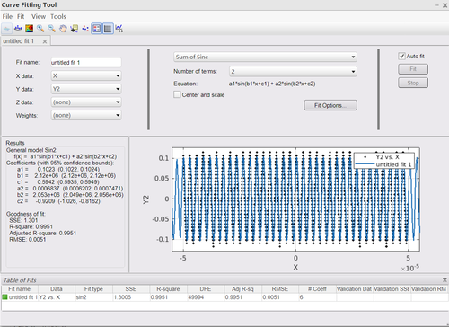
Here we save data from an oscilloscope(the signal from detector). Because the sampling time is much shorter than the period of car moving, we can treat the frequency of sine signal unchanged. We can fit the line and get the frequency of signal directly. Then, the ratio gives us the ratio of laser frequency. | |||
In a 100 <math>\mu s</math> time duration, two beat signals are sine fitted and the ratio of resulted frequency is the ratio of two lasers' frequency. | |||
<gallery widths=500px heights=400px> | |||
File:wavemeter Plot.png|thumb|right|800px|1550nm&701nm plot | |||
</gallery> | |||
<gallery widths=500px heights=400px> | |||
File:wavemeter Y1.png|thumb|right|800px|701nm fitting | |||
</gallery> | |||
<gallery widths=500px heights=400px> | |||
File:wavemeter Y2.png|thumb|right|800px|1550nm fitting | |||
</gallery> | |||
<math>\frac{1550}{701}=2.2111</math> and from fitted line we get ratio <math>\frac{4.698}{2.12}=2.2160</math> | |||
'''Comment''': Whenever possible, try to specify an uncertainty of your measurement result. In this method of determining the wavelength, it would likely be the uncertainty of +/-1 in the zero transitions during a fixed periode of the test beam. Not sure how your code exactly works, but you may or may not have to consider an uncertainty of +/-1 in the reference counts as well. The latter uncertainty you could remove if you count a fixed number of reference events, and use it to control a gate window for the test counts.... | |||
===Arduino counter=== | |||
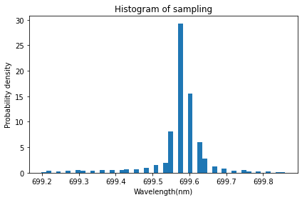
For Arduino counter, because we do not limit the start point of counting(do not make sure two signals have the same phase), counts may be different. There is also fluctuation in counts. So we read 20000 samples and plot the histogram here. | |||
<gallery widths=500px heights=400px> | |||
File:Wavemeter_histogram_of_sampling.png|thumb|right|800px|1550nm&701nm plot | |||
</gallery> | |||
The average result shows a ratio of wavelength <math>2.2157</math>, the same as the result from the fitting method. | |||
==Future work== | |||
There exist several problems to be solved here. | |||
First, the wavelength of our laser is unknown. So we can only get a ratio and can not get an absolute value. We plan to use a 804nm laser as reference in the future because this laser is locked and we can read the wavelength from the wavemeter in our lab. | |||
Second, in the result from Arduino board, the result shows discrete distribution. The space between boxes is limited by max counts set in Arduino code. If we want to get a higher resolution, we need higher max counts, which means a longer sampling time. | |||
Third, It is necessary to write an interface window to make this system easier to use. This window should allow people choose max counts and average numbers. | |||
Our project gives a preliminary result here. It can be improved by solving these problems. | |||
==History== | ==History== | ||
===Mar 9=== | ===Mar 9=== | ||
| Line 96: | Line 172: | ||
We test our pull-push solenoids and optical switch. We aim to use Arduino UNO as our controller. Today we test using an optical switch to generate the voltage signal. | We test our pull-push solenoids and optical switch. We aim to use Arduino UNO as our controller. Today we test using an optical switch to generate the voltage signal. | ||
===Mar 16=== | ===Mar 16=== | ||
| Line 131: | Line 203: | ||
Make one 90 curved copper pipe and try it. But it is so heavy that the car tilts and touches one side of the air track. It is better not to use this. We find a curved plastic pipe which is better to do this. We also borrow a soft pipe and the compression spring from Kai's Lab(the spring we bought before is too hard, the k is too high). | Make one 90 curved copper pipe and try it. But it is so heavy that the car tilts and touches one side of the air track. It is better not to use this. We find a curved plastic pipe which is better to do this. We also borrow a soft pipe and the compression spring from Kai's Lab(the spring we bought before is too hard, the k is too high). | ||
[[File:Wavemeter_airtrack.jpeg|300px|thumb|right|Air track and car for the wavemeter]] | |||
===Apr 8=== | ===Apr 8=== | ||
The clock frequency is designed to be 16MHz so theoretically signal with a lower frequency than 16MHz can all be counted. It also reminds me that the timer inside the chip can be chosen as the counter. Choosing the timer inside needs an understanding of the register inside the microcontroller. Basically, registers can store some bits and the value of these bits can determine how the chip works. Details about this can be found in https://ww1.microchip.com/downloads/en/DeviceDoc/Atmel-7810-Automotive-Microcontrollers-ATmega328P_Datasheet.pdf | The clock frequency is designed to be 16MHz so theoretically signal with a lower frequency than 16MHz can all be counted. It also reminds me that the timer inside the chip can be chosen as the counter. Choosing the timer inside needs an understanding of the register inside the microcontroller. Basically, registers can store some bits and the value of these bits can determine how the chip works. Details about this can be found in https://ww1.microchip.com/downloads/en/DeviceDoc/Atmel-7810-Automotive-Microcontrollers-ATmega328P_Datasheet.pdf | ||
| Line 136: | Line 210: | ||
Use this method as our counter. It is found the board can work pretty well when we use two MHz signals as input from a function generator. Now the control part can be added in. | Use this method as our counter. It is found the board can work pretty well when we use two MHz signals as input from a function generator. Now the control part can be added in. | ||
===Apr 9=== | ===Apr 9=== | ||
The picture shows the basic idea about our circuit. Two optical switches and one solenoid are connected to our Arduino UNO board. We want to make sure the board stops counting when the car | The picture shows the basic idea about our circuit. [[File:Wavemeter_test_circuit1.jpeg|300px|thumb|right|The circuit for our wavemeter]]Two optical switches and one solenoid are connected to our Arduino UNO board. We want to make sure the board stops counting when the car moves to the edge. So the optical switch 1 is connected to the INT1 pin of Atmega328p which is used to request an interrupt<ref>http://gammon.com.au/interrupts</ref> to pause counting when the signal changes. The optical switch 0 is connected to INT0 and can also pause counting. INT0 is also used to control solenoid. This pull push solenoid is on when the car reaches the edge and pushes the car back. We use a simple transistor to control it. | ||
The result shows our board can count the risings in signal and when one counting reaches a maximum value we set before it will show and then clear the counting. | The result shows our board can count the risings in signal and when one counting reaches a maximum value we set before it will show and then clear the counting. | ||
Use two signals from a function generator as input. One is 1.2MHz and the other one is 1MHz. | Use two signals from a function generator as input. One is 1.2MHz and the other one is 1MHz. The counting from our board is 5120000 and 4266671. The ratio is 1.19999878125. The maximum value of counting, 5120000, can be changed to get different precision. | ||
===Apr 12=== | ===Apr 12=== | ||
Test the circuit which controls the car. Change the position of optical switch 0 a little to make the car keep moving. The result shows the car can move at least several hours if the air pressure is suitable. | |||
===Apr 14=== | ===Apr 14=== | ||
make a board instead of using the breadboard. | Use a PCB board found in the workshop and make a board instead of using the breadboard in case someone messes up our circuit. | ||
[[File:wavemeter_circuit_v2.jpg| | [[File:wavemeter_circuit_v2.jpg|300px|right|thumb|circuit of wavemeter]] | ||
===Apr 16=== | |||
Finish setting up for optics preliminarily. Now we use 701 laser to test our wavemeter. | |||
===Apr 19=== | |||
Check the signal from detectors. The signal from 1550nm reference laser is not stable while the signal from 701nm laser is stable. That is because we set up 1550 first and now the optics is optimized for 701 laser. When the car moves, the reference signal shows an oscillating. It is also a problem that the signals are too small for our counter to work. We need to process the signal first. | |||
===Apr 21=== | |||
Because the interference is not ideal so there is a DC voltage in our signal. We test a high pass filter to do this. | |||
===Apr 23=== | |||
Make a board to process the signal. The board is designed to filter dc signal and amplified the sine signal. The output is designed to be a 0-5V square wave which is more suitable for our counters. | |||
===Apr 26=== | |||
Test the wavemeter today. The circuit and counter work well but the result is wrong. The problem is from 1550 reference laser. Because this signal is not stable. When the signal is very small, the counter will miss counts. Then the counts for 1550 will be smaller than the actual number which means our result will be smaller than the real value. So need to check our setup. | |||
===Apr 28=== | |||
Check the setup and set smaller max counts. Now the board can work well. | |||
==Reference== | |||
<references /> | |||
==Code== | ==Code== | ||
Here is the code for Arduino IDE. | |||
<pre> | |||
//these two lines are used to disable the timer0 defination used in Arduino board. wiring.c should be changed. | |||
//signal <3MHz 2.5V crossing Vpp>1V | |||
#define _DISABLE_ARDUINO_TIMER0_INTERRUPT_HANDLER_ | |||
#include <wiring.c> | |||
volatile int counter_0_ovf = 0; //use timer 0 8bit count 256*ovf pin4 detector 0 | |||
volatile int counter_1_ovf = 0; //use timer 1 16bit count 65536*ovf pin5 detector 1 | |||
volatile long counter0_ovf_result = 0;//store ovf value | |||
volatile long counter1_ovf_result = 0;//store ovf value | |||
volatile int counter0 = 0;//timer0 value | |||
volatile int counter1 = 0;//timer1 value | |||
bool car_state = true; //state of car, initial value true | |||
bool counter0_state = false;//state flag for counter0, initial value false | |||
bool counter1_state = false;//state flag for counter1, initial value false | |||
int state = 0; | |||
long MaxCount0_ovf = 10240; //define max ovf value for counter0 | |||
long MaxCount1_ovf = MaxCount0_ovf*256/65536; //define max ovf value for counter1 | |||
void counter_reset(){ | |||
//clear counter | |||
TCNT0 = 0; | |||
TCNT1 = 0; | |||
//clear ovf_value | |||
counter_0_ovf = 0; | |||
counter_1_ovf = 0; | |||
} | |||
void setup() { | |||
//initila serial setting | |||
Serial.begin(9600); | |||
cli();//disable all interrupt | |||
//enable timer 0 and timer 1 by clearing PRTIM | |||
PRR&=~((1<<PRTIM0)|(1<<PRTIM1)); | |||
//set timer 0 | |||
TCCR0B|=(1<<CS00)|(1<<CS01)|(1<<CS02); //External clock source on T0 pin4. Clock on rising edge. | |||
//clear WGM to set normal mode | |||
TCCR0A&=~((1<<WGM01)|(1<<WGM00)); | |||
TCCR0B&=~(1<<WGM02); | |||
TIMSK0|= (1<<TOIE0); //overflow interrupt is enabled | |||
//set timer 1 | |||
TCCR1B|=(1<<CS10)|(1<<CS11)|(1<<CS12); //External clock source on T1 pin5. Clock on rising edge. | |||
//clear WGM to set normal mode | |||
TCCR1A&=~((1<<WGM11)|(1<<WGM10)); | |||
TCCR1B&=~((1<<WGM13)|(1<<WGM12)); | |||
TIMSK1|= (1<<TOIE1); //overflow interrupt is enabled | |||
//set external interrupt for coil control and pause counting, signal source: optical switch0. use INT0 | |||
EIMSK &=~ (1<<INT0);//disable | |||
EICRA |= (1<<ISC00)|(1<<ISC01);//The rising edge of INT0 generates an interrupt request | |||
EIFR |= (1<<INTF0);//clear the flag | |||
EIMSK |= (1<<INT0);//enable | |||
//set external interrupt pause counting, signal source: optical switch1. use INT1 | |||
EIMSK &=~ (1<<INT1);//disable | |||
EICRA |= (1<<ISC10)|(1<<ISC11);//The rising edge of INT1 generates an interrupt request | |||
EIFR |= (1<<INTF1);//clear the flag | |||
EIMSK |= (1<<INT1);//enable | |||
//initial the coil(default: off) | |||
DDRB |= (1<<DDB0);//pin set as output to control coil | |||
PORTB&=~(1<<PORTB0);//off | |||
sei();//enable interrupt | |||
} | |||
ISR(INT0_vect){ | |||
//toggle the state of car | |||
car_state = !car_state; | |||
//turn on/off the counter | |||
PRR^=((1<<PRTIM0)|(1<<PRTIM1)); | |||
//toggle the coil | |||
PORTB^=(1<<PINB0); | |||
} | |||
ISR(INT1_vect){ | |||
//toggle the state of car | |||
car_state = !car_state; | |||
//toggle the switch to control counter | |||
PRR^=((1<<PRTIM0)|(1<<PRTIM1)); | |||
} | |||
ISR(TIMER0_OVF_vect){ | |||
counter_0_ovf++; | |||
if (counter_0_ovf<MaxCount0_ovf){ | |||
counter0_state = false;//counter0 not ready | |||
} | |||
else{ | |||
counter0_ovf_result = counter_0_ovf; | |||
counter1_ovf_result = counter_1_ovf; | |||
counter0_state = true;//counter0 ready | |||
counter0 = 0; | |||
counter1 = TCNT1;//restore counter1 value | |||
counter_reset(); | |||
} | |||
} | |||
ISR(TIMER1_OVF_vect){ | |||
counter_1_ovf++; | |||
if (counter_1_ovf<MaxCount1_ovf){ | |||
counter1_state = false;//counter1 not ready | |||
} | |||
else{ | |||
counter1_ovf_result = counter_1_ovf; | |||
counter0_ovf_result = counter_0_ovf; | |||
counter1_state = true;//counter1 ready | |||
counter1 = 0; | |||
counter0 = TCNT0;//restore counter0 value | |||
counter_reset(); | |||
} | |||
} | |||
void loop() { | |||
state = (car_state&&(counter0_state||counter1_state)); | |||
switch(state){ | |||
case 0: | |||
//not ready | |||
break; | |||
case 1: | |||
//result ready | |||
//send counts to computer | |||
Serial.println("counts pin, pin4 and pin5"); | |||
Serial.println((counter0_ovf_result)*256+counter0); | |||
Serial.println((counter1_ovf_result)*65536+counter1); | |||
//clear state in case the board repeats output | |||
counter0_state = false; | |||
counter1_state = false; | |||
break; | |||
} | |||
} | |||
</pre> | |||
Here is the jupyter notebook Python2 code for getting result: | |||
<pre> | |||
import serial | |||
import numpy as np | |||
from matplotlib import pyplot as plt | |||
arduino = serial.Serial('COM5', 9600, timeout=.1) | |||
def group_sampling(lines): | |||
counter0=[] | |||
counter1=[] | |||
i = 0 | |||
while i+2 < len(lines): | |||
if lines[i] == 'counts pin, pin4 and pin5': | |||
counter0.append(float(lines[i+1])) | |||
counter1.append(float(lines[i+2])) | |||
i += 1 | |||
return [np.array(counter0),np.array(counter1)] | |||
w0 = 1550e-9 #wavelength of reference laser | |||
#read data | |||
Maxsampling = 20000 #groups of sampling | |||
lines=[] | |||
i = 0 | |||
for i in list(range(3*Maxsampling)): | |||
read = arduino.readline()[:-2] | |||
if read: | |||
lines.append(read) | |||
[counter0,counter1] = group_sampling(lines) | |||
ratio = counter0/counter1 | |||
ratio.sort() | |||
ratio = ratio[10000:-1000] | |||
result = w0*ratio | |||
f = 299792458/result/1e6 | |||
sample = result | |||
fig, ax = plt.subplots() | |||
num_bins = 50 | |||
# the histogram of the data | |||
n, bins, patches = ax.hist(sample, num_bins, density = True) | |||
# add a 'best fit' line | |||
#y = ((1 / (np.sqrt(2 * np.pi) * sigma)) * | |||
# np.exp(-0.5 * (1 / sigma * (bins - mu))**2)) | |||
#ax.plot(bins, y, '--') | |||
ax.set_xlabel('Wavelength') | |||
ax.set_ylabel('Probability density') | |||
ax.set_title(r'Histogram of sampling: $\mu={:.2f}$, $\sigma={:.2f}$'.format(np.mean(sample),np.std(sample))) | |||
# Tweak spacing to prevent clipping of ylabel | |||
fig.tight_layout() | |||
plt.show() | |||
</pre> | |||
Latest revision as of 19:20, 5 May 2021
This project aims to build a wavemeter which can be used to measure laser in our lab precisely.
Team: Qin Qichen, Zhao Qi, Zhang Zhao.
Introduction
There are many methods to measure the wavelength of laser. One easy idea is to use an interferometer. The fringes of interference is associated with wavelength of laser. So by comparing it with the result of a reference laser the wavelength can be measured. Now there is something wrong with the wavemeter in our lab. Hence, we aim to build a wavemeter to measure laser in our lab. The range of wavelength our wavemeter can detect aim to be around 1100nm - 1700nm, determined by optics. A precision around 100MHz is expected.
Theory
Michelson interferometer is a good tool to measure the length if there is a good laser. Similarly, it can also be used to measure the unknown wavelength of a laser by calculating the ratio of wavelengths between the unknown and a known laser. Here we use a 1550nm laser as our reference. By counting zeros in the signal, we can get the ratio between wavelengths.

In Michelson interferometer[1], an input beam is splitted into two and reflected back by their respective mirror. The two beams with a phase difference caused by travelling different optical path lengths would form an interference pattern after overlapping. If we change the optical path length difference of the two beams, i.e. change the length of one arm by moving the mirror, the interference pattern would change simultaneously.
Consider the planar wave case, the two reflected beams could be written as and , where is the amplitude of the input beam, is the angular frequency, is the wavenumber, is the refractive index of air, is the length of one constant arm and is the length difference changing with time of the other arm.
Then the total electrical field at the output would be
The intensity would thus be
For , the number of zero-crossings of the interference pattern would be . According to this equation, we can relate the ratio of wavelengths of two lasers and with their number of zero-crossings as
.
Components

Optics
- List of all the optic components used
- Silver mirror x6 (to adapt broadband laser that might be measured)
- BB1-E04 mirror x2 (for 1550nm reference laser)
- 50/50 Beamsplitter 1100nm-1600nm x1
- C220-c Aspherical lens x2 (for fiber input of two lasers)
- TS975M-M01B Retroreflector x2
- f50mm lens x1 (for unknown-laser detector)
- f35mm lens x1 (for 1550nm detector)
- PDA10CS-EC detector x1
- PDA50B-EC detector x1
Air track
The whole setup including air track and optics is built on a 750mmx750mm breadboard table. The aluminum linear stage is 550mmx50mm with a 150mmx50mm sledge sliding on its V-shape surface. The friction is reduced by producing an air cushion between the two surfaces using 10 small holes on the bottom of sledge that is provided with compressed air via a silicon tube. Two springs are attached to both ends of the sledge and fixed around two long screws. Besides the force provided by springs when reflected from ends, the kinetic energy loss is also compensated by a small push pull solenoid fixed on one end of the stage. Two optical switches are mounted on board to detect the signal when sledge reaches ends by a piece of paper fixed on sledge, controlling the solenoid.
Signal Process
The circuit for processing signal. The signals generated by photodetectors are small and dc biased. To enable our counter, we need to transfer the signal to a 0-5V signal. We first use a high pass filter to get rid of the dc part. Then a monolithic amplifier is used to amplify the ac signal before we put it into our comparator. The comparator is used to generate the 5V signal. The output port of LM339AN can be seen as a transistor so use a pullup resistor connected to 5V we can accomplish it.
-
 signal processing circuit

Comment: Congratulation, obviously it worked ;) However, the MAR amplifiers would need a resistor at the positive supply feeding in DC current for them to actually amplify the signal. Maybe you did not need it in the case here... Also, keep in mind these amplifiers are internally terminated with 50 Ohm to ground: The additional resistors with 150 Ohm at their input only lowers the total input impedance to 1/(1/50+1/150)=37.5Ohm, so you likely have a higher cutoff frequency than what you thought. But hey, it worked!
- Components we use

- 2 Resistors for high pass filter
- 2 Capacitors for high pass filter
- 2 Resistors for low pass filter
- 2 Capacitors for low pass filter
- 1 Quad Differential Comparators LM339AN
- 2 Monolithic Amplifiers MAR-3SM+
- 1 Voltage Regulator L7805SCV
- 2 Potentiometer
Control Circuit
The schematic of the circuit for control is shown below. Arduino UNO[2] board is used to control and count signals and should be connected to a computer to power it and get reading. Two optical switches are used to get rid of signal change when car gets pushed back. The optical switch 0 is also used to turn on/off solenoid. A push pull solenoid is used to push the car and compensate for energy loss in motion.
-
 control circuit

- Components we use
- 2 Optical switches OPB881T55Z
- 1 Push-Pull solenoid TAU0730TM-14
- 2 Optical detectors PDA10CS-EC and PDA50B-EC
- 2 Resistors for photodiode
- 2 Resistors for phototransistor
- 1 Resistor for transistor base
- 1 Transistor 2N2222A
- 1 diode to protect 1N4007G
-
 optical switch
 -
 push pull solenoid


Program
The main program consists of two parts.

One is to control the car. When the car passes across the optical switch 0 and move to the edge, the program will receive a signal change from OS0 and then turn on the solenoid. Then the small solenoid will be driven and push the car. So the position of optical switch 0 should be suitable because if the solenoid is on when the car moves towards the edge, the car will be decelerated. The right timing is to push the car when the spring is compressed to the minimum length. This can be done by changing the position of OS0.
The other part is two counters, for reference and measured laser. We make use of Arduino UNO to do this. There are three timers inside Atmega328P[3](this chip is the core controller of Arduino UNO). Timer0 and Timer2 are 8bit timer and Timer1 is a 16bit timer. Normally when you enable the timer, it will use the internal 16MHz clock and count the clock signal. For example, if you set no prescale(which means the clock frequency is 16/1 = 16Mhz), the timer register will increase every 1/16M second. Then it will be cleared when its value overflows. For 8 bit timer the range of register is from 0 to 255. Then we use these timers to count the rising in the interferometer signal. As tested before, it should be noticed the frequency should be no more than 3MHz and the transition must cross 2.5V and Vpp must be larger than 1V. Otherwise, the timer will lose signals.
As shown here, the initial state of the wavemeter should be like this, the car should be between two optical switches. That's because the setting in code. The circuit does not know where the car is and it only knows whether the car passes across optical switches. So I set the initial state variable as 1 which means the car is between two optical switches and the counters are working. The program will pause the counter by cutting off power for counters when the car passes across optical switches. Because we want to get rid of the signal when the car changes its direction.
Result
Here we use 1550nm laser as our reference, 701nm laser as a measured laser to test the wavemeter. We need to clarify here that these two lasers are available in our lab now but not locked. So we do not know the real number of the wavelength. There are two methods to count fringes. One way is to use an oscilloscope to save fringes and process data on PC. The other way is to use our Arduino board to count and send counts to the computer automatically. Here we first use an oscilloscope to test our setup. Our result shows the ratios from two methods are in accordance, which shows the counter we made works at least.
Signal
Here is the signal from detector directly.
-
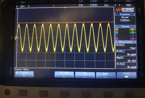 Signal from wavemeter

As said in electronic section, we use a circuit to amplify and reshape the signal. After processing, the signal is shown below:
-
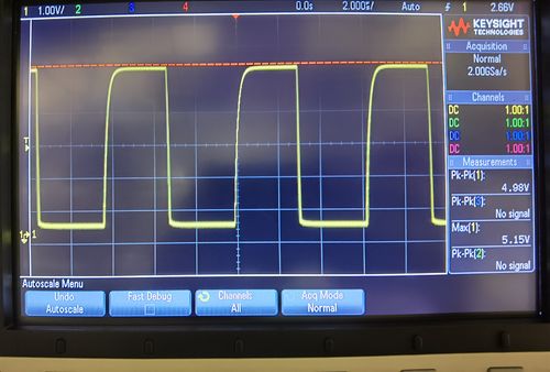 Signal from wavemeter

Oscilloscope
Here we save data from an oscilloscope(the signal from detector). Because the sampling time is much shorter than the period of car moving, we can treat the frequency of sine signal unchanged. We can fit the line and get the frequency of signal directly. Then, the ratio gives us the ratio of laser frequency. In a 100 time duration, two beat signals are sine fitted and the ratio of resulted frequency is the ratio of two lasers' frequency.
-
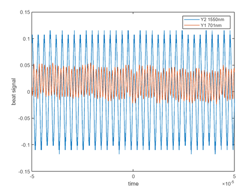 1550nm&701nm plot

-
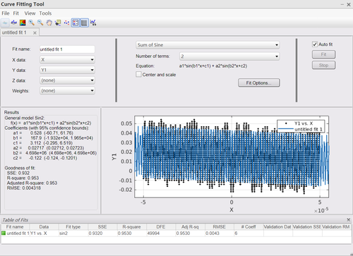 701nm fitting

-
 1550nm fitting

and from fitted line we get ratio
Comment: Whenever possible, try to specify an uncertainty of your measurement result. In this method of determining the wavelength, it would likely be the uncertainty of +/-1 in the zero transitions during a fixed periode of the test beam. Not sure how your code exactly works, but you may or may not have to consider an uncertainty of +/-1 in the reference counts as well. The latter uncertainty you could remove if you count a fixed number of reference events, and use it to control a gate window for the test counts....
Arduino counter
For Arduino counter, because we do not limit the start point of counting(do not make sure two signals have the same phase), counts may be different. There is also fluctuation in counts. So we read 20000 samples and plot the histogram here.
-
 1550nm&701nm plot

The average result shows a ratio of wavelength , the same as the result from the fitting method.
Future work
There exist several problems to be solved here.
First, the wavelength of our laser is unknown. So we can only get a ratio and can not get an absolute value. We plan to use a 804nm laser as reference in the future because this laser is locked and we can read the wavelength from the wavemeter in our lab.
Second, in the result from Arduino board, the result shows discrete distribution. The space between boxes is limited by max counts set in Arduino code. If we want to get a higher resolution, we need higher max counts, which means a longer sampling time.
Third, It is necessary to write an interface window to make this system easier to use. This window should allow people choose max counts and average numbers.
Our project gives a preliminary result here. It can be improved by solving these problems.
History
Mar 9
We find the optics for our wavemeter and order the retroreflectors. The design files of our air track and car are sent to Bob.
We test our pull-push solenoids and optical switch. We aim to use Arduino UNO as our controller. Today we test using an optical switch to generate the voltage signal.
Mar 16
Arduino UNO is tested to do the counter. We try to use the simple functions provided by Arduino compiler environment to do this. The idea is to detect the rising of the signal. So I make the comparison between two samplings with a given time interval to see if there is a rising. The problem is this method is too slow. The function provided by the compiler is actually a bunch of pieces of the atomical operations. The time interval set by function is also limited by an internal timer of the board.
There are two types of timers in this Arduino UNO board, which are actually provided by the microcontroller chip Atmega328P. The chip has an internal clock with 16MHz frequency. Theoretically, our signal is around 1MHz if assuming the speed of our car is around 1m/s. So it seems feasible if we use the internal clock to do this counter. Need to read documents and search to see how other people do this.
Mar 29
Sampling and comparing the signal is not good enough to do the counter. This method is useful only for very slow signals such as 1kHz. If the frequency of our signal is 1MHz, if we want to do the counting by comparing the sampling, our sampling should be at least 2MHz to capture all rising. But when we compare the executing of those codes can waste a lot of time, then we will miss a lot of rising signal. So it is not a good idea.
I check some useful documents. It seems use port manipulation will minimize the time used to do the read and write. I can also use the interrupt which is associated with a timer to do some tasks. A good instruction about this can be seen on the sites below.
https://www.arduino.cc/en/Reference/PortManipulation
https://www.instructables.com/Arduino-and-Port-Manipulation/
https://www.instructables.com/Arduino-Timer-Interrupts/
http://gammon.com.au/interrupts
Apr 5
Bob finished the mechanical work. We get our air track and car. We are beginning to set up the air track.
Apr 6
We use compressed air in our lab as our air source. we put the car on the air track. But their are two problems here.
First, the air port of the car is on one side so the pipe may touch some optics. So we need an L shape adapter to make the pipe vertical.
Then, the pipe connected to the car is hard, which means when we move the car it will be forced by the pipe. We need to find a softer pipe,
Murray suggests using a 90 curved copper pipe to connect the car.
Apr 7
Tried the method in https://www.arduino.cc/reference/en/language/functions/external-interrupts/attachinterrupt/. Use the signal to trigger the interrupt. I use two signals from the function generator to test. The result is it can detect a signal no more than 100kHz. So this method is not good and we still need to find a way to do the counting.
Make one 90 curved copper pipe and try it. But it is so heavy that the car tilts and touches one side of the air track. It is better not to use this. We find a curved plastic pipe which is better to do this. We also borrow a soft pipe and the compression spring from Kai's Lab(the spring we bought before is too hard, the k is too high).

Apr 8
The clock frequency is designed to be 16MHz so theoretically signal with a lower frequency than 16MHz can all be counted. It also reminds me that the timer inside the chip can be chosen as the counter. Choosing the timer inside needs an understanding of the register inside the microcontroller. Basically, registers can store some bits and the value of these bits can determine how the chip works. Details about this can be found in https://ww1.microchip.com/downloads/en/DeviceDoc/Atmel-7810-Automotive-Microcontrollers-ATmega328P_Datasheet.pdf
Use this method as our counter. It is found the board can work pretty well when we use two MHz signals as input from a function generator. Now the control part can be added in.
Apr 9
The picture shows the basic idea about our circuit.

Two optical switches and one solenoid are connected to our Arduino UNO board. We want to make sure the board stops counting when the car moves to the edge. So the optical switch 1 is connected to the INT1 pin of Atmega328p which is used to request an interrupt[4] to pause counting when the signal changes. The optical switch 0 is connected to INT0 and can also pause counting. INT0 is also used to control solenoid. This pull push solenoid is on when the car reaches the edge and pushes the car back. We use a simple transistor to control it.
The result shows our board can count the risings in signal and when one counting reaches a maximum value we set before it will show and then clear the counting.
Use two signals from a function generator as input. One is 1.2MHz and the other one is 1MHz. The counting from our board is 5120000 and 4266671. The ratio is 1.19999878125. The maximum value of counting, 5120000, can be changed to get different precision.
Apr 12
Test the circuit which controls the car. Change the position of optical switch 0 a little to make the car keep moving. The result shows the car can move at least several hours if the air pressure is suitable.
Apr 14
Use a PCB board found in the workshop and make a board instead of using the breadboard in case someone messes up our circuit.

Apr 16
Finish setting up for optics preliminarily. Now we use 701 laser to test our wavemeter.
Apr 19
Check the signal from detectors. The signal from 1550nm reference laser is not stable while the signal from 701nm laser is stable. That is because we set up 1550 first and now the optics is optimized for 701 laser. When the car moves, the reference signal shows an oscillating. It is also a problem that the signals are too small for our counter to work. We need to process the signal first.
Apr 21
Because the interference is not ideal so there is a DC voltage in our signal. We test a high pass filter to do this.
Apr 23
Make a board to process the signal. The board is designed to filter dc signal and amplified the sine signal. The output is designed to be a 0-5V square wave which is more suitable for our counters.
Apr 26
Test the wavemeter today. The circuit and counter work well but the result is wrong. The problem is from 1550 reference laser. Because this signal is not stable. When the signal is very small, the counter will miss counts. Then the counts for 1550 will be smaller than the actual number which means our result will be smaller than the real value. So need to check our setup.
Apr 28
Check the setup and set smaller max counts. Now the board can work well.
Reference
Code
Here is the code for Arduino IDE.
//these two lines are used to disable the timer0 defination used in Arduino board. wiring.c should be changed.
//signal <3MHz 2.5V crossing Vpp>1V
#define _DISABLE_ARDUINO_TIMER0_INTERRUPT_HANDLER_
#include <wiring.c>

volatile int counter_0_ovf = 0; //use timer 0 8bit count 256*ovf     pin4 detector 0
volatile int counter_1_ovf = 0; //use timer 1 16bit count 65536*ovf  pin5 detector 1
volatile long counter0_ovf_result = 0;//store ovf value
volatile long counter1_ovf_result = 0;//store ovf value
volatile int counter0 = 0;//timer0 value
volatile int counter1 = 0;//timer1 value


bool car_state = true; //state of car, initial value true
bool counter0_state = false;//state flag for counter0, initial value false
bool counter1_state = false;//state flag for counter1, initial value false

int state = 0;

long MaxCount0_ovf = 10240; //define max ovf value for counter0
long MaxCount1_ovf = MaxCount0_ovf*256/65536; //define max ovf value for counter1

void counter_reset(){
  //clear counter
  TCNT0 = 0;
  TCNT1 = 0;
  //clear ovf_value
  counter_0_ovf = 0;
  counter_1_ovf = 0;
}

void setup() {
  //initila serial setting
  Serial.begin(9600);

  cli();//disable all interrupt

  //enable timer 0 and timer 1 by clearing PRTIM
  PRR&=~((1<<PRTIM0)|(1<<PRTIM1));

  //set timer 0
  TCCR0B|=(1<<CS00)|(1<<CS01)|(1<<CS02); //External clock source on T0 pin4. Clock on rising edge.
  //clear WGM to set normal mode
  TCCR0A&=~((1<<WGM01)|(1<<WGM00));
  TCCR0B&=~(1<<WGM02);
  TIMSK0|= (1<<TOIE0); //overflow interrupt is enabled

  //set timer 1
  TCCR1B|=(1<<CS10)|(1<<CS11)|(1<<CS12); //External clock source on T1 pin5. Clock on rising edge.
  //clear WGM to set normal mode
  TCCR1A&=~((1<<WGM11)|(1<<WGM10));
  TCCR1B&=~((1<<WGM13)|(1<<WGM12));
  TIMSK1|= (1<<TOIE1); //overflow interrupt is enabled

  //set external interrupt for coil control and pause counting, signal source: optical switch0. use INT0
  EIMSK &=~ (1<<INT0);//disable
  EICRA |= (1<<ISC00)|(1<<ISC01);//The rising edge of INT0 generates an interrupt request
  EIFR |= (1<<INTF0);//clear the flag
  EIMSK |= (1<<INT0);//enable

  //set external interrupt pause counting, signal source: optical switch1. use INT1
  EIMSK &=~ (1<<INT1);//disable
  EICRA |= (1<<ISC10)|(1<<ISC11);//The rising edge of INT1 generates an interrupt request
  EIFR |= (1<<INTF1);//clear the flag
  EIMSK |= (1<<INT1);//enable

  //initial the coil(default: off)
  DDRB |= (1<<DDB0);//pin set as output to control coil
  PORTB&=~(1<<PORTB0);//off

  sei();//enable interrupt
}

ISR(INT0_vect){
  //toggle the state of car
  car_state = !car_state;
  //turn on/off the counter
  PRR^=((1<<PRTIM0)|(1<<PRTIM1));
  //toggle the coil
  PORTB^=(1<<PINB0);
}

ISR(INT1_vect){
  //toggle the state of car
  car_state = !car_state;
  //toggle the switch to control counter
  PRR^=((1<<PRTIM0)|(1<<PRTIM1));
}

ISR(TIMER0_OVF_vect){
    counter_0_ovf++;
  if (counter_0_ovf<MaxCount0_ovf){
    counter0_state = false;//counter0 not ready
  }
  else{
    counter0_ovf_result = counter_0_ovf;
    counter1_ovf_result = counter_1_ovf;
    counter0_state = true;//counter0 ready
    counter0 = 0;
    counter1 = TCNT1;//restore counter1 value
    counter_reset();
  }
}

ISR(TIMER1_OVF_vect){
  counter_1_ovf++;
  if (counter_1_ovf<MaxCount1_ovf){
    counter1_state = false;//counter1 not ready
  }
  else{
    counter1_ovf_result = counter_1_ovf;
    counter0_ovf_result = counter_0_ovf;
    counter1_state = true;//counter1 ready
    counter1 = 0;
    counter0 = TCNT0;//restore counter0 value
    counter_reset();
  }
}

void loop() {
  state = (car_state&&(counter0_state||counter1_state));
  switch(state){
    case 0:
    //not ready
    break;
    case 1:
    //result ready
    //send counts to computer
    Serial.println("counts pin, pin4 and pin5");
    Serial.println((counter0_ovf_result)*256+counter0);
    Serial.println((counter1_ovf_result)*65536+counter1);
    //clear state in case the board repeats output
    counter0_state = false;
    counter1_state = false;

    break;
  }
}
Here is the jupyter notebook Python2 code for getting result:
import serial
import numpy as np
from matplotlib import pyplot as plt

arduino = serial.Serial('COM5', 9600, timeout=.1)

def group_sampling(lines):
    counter0=[]
    counter1=[]
    i = 0
    while i+2 < len(lines):
        if lines[i] == 'counts pin, pin4 and pin5':
            counter0.append(float(lines[i+1]))
            counter1.append(float(lines[i+2]))
        i += 1
    return [np.array(counter0),np.array(counter1)]

w0 = 1550e-9 #wavelength of reference laser

#read data
Maxsampling = 20000 #groups of sampling
lines=[]
i = 0
for i in list(range(3*Maxsampling)):
    read = arduino.readline()[:-2]
    if read:
        lines.append(read)

[counter0,counter1] = group_sampling(lines)

ratio = counter0/counter1
ratio.sort()
ratio = ratio[10000:-1000]

result = w0*ratio
f = 299792458/result/1e6

sample = result

fig, ax = plt.subplots()

num_bins = 50

# the histogram of the data
n, bins, patches = ax.hist(sample, num_bins, density = True)

# add a 'best fit' line
#y = ((1 / (np.sqrt(2 * np.pi) * sigma)) *
#     np.exp(-0.5 * (1 / sigma * (bins - mu))**2))
#ax.plot(bins, y, '--')
ax.set_xlabel('Wavelength')
ax.set_ylabel('Probability density')
ax.set_title(r'Histogram of sampling: $\mu={:.2f}$, $\sigma={:.2f}$'.format(np.mean(sample),np.std(sample)))

# Tweak spacing to prevent clipping of ylabel
fig.tight_layout()
plt.show()