|
|
| Line 11: |
Line 11: |
| ==Characteristic Parameters of an Etalon== | | ==Characteristic Parameters of an Etalon== |
| [[How does an etalon work]] | | [[How does an etalon work]] |
| The performance of etalon is characterized by several main parameters: including visibility (V), free spectral range (FSR), full width half maximum (FWHM), and central wavelength.
| |
|
| |
| Suppose that the <math>a_1</math>, <math>a_2</math>, <math>a_3</math> are the electrical field intensity of input, oscillating, output light.
| |
| [[File:Etalon_principle.jpg]]
| |
|
| |
| The relationship is as follows
| |
|
| |
| <math>a_2=ta_1+r^2a_2e^{-i\phi}</math>
| |
|
| |
| <math>a_3=ta_2</math>
| |
|
| |
| Where \phi means that phase delay in the cavity and the gap between two reflective surfaces is d.
| |
|
| |
| <math>\phi=2kd=2\frac{2\pi}{\lambda}d</math>
| |
|
| |
| From the upper two equations, we have
| |
|
| |
| <math>a_2=a_1\frac{t}{1-r^2e^{-i\phi}}</math>
| |
|
| |
| <math>a_3=a_1\frac{t^2}{1-r^2e^{i\phi}}</math>
| |
|
| |
| Then, we can calculate the transmission ratio:
| |
|
| |
| <math>T_R=|\frac{a_3}{a_1}|=|\frac{t^2}{1-r^2e^{i\phi}}|^2=\frac{t^4}{(1-r^2e^{i\phi})^2+(r^2sin\phi)^2}=\frac{t^4}{1-r^2-2rcos\phi}</math>
| |
|
| |
| Here, we have <math>cos\phi=1-2sin^2\frac{\phi}{2}</math>
| |
|
| |
| So, <math>T_R</math> can be simplified as follows
| |
|
| |
| <math>T_R=\frac{t^4}{(1-r^2)^2+4r^2sin^2\frac{\phi}{2}}=\frac{1}{1+\frac{4r^2}{t^4}sin^2\frac{\phi}{2}}</math>
| |
|
| |
| Here, we define a new parameter: <math>F=\frac{4r^2}{t^4}</math>, which is called coefficient finesse.
| |
|
| |
| So, <math>T_R=\frac{1}{1+Fsin^2\frac{\phi}{2}}</math>
| |
|
| |
| Since we already have the expression of transmission (T), we can also derive some important parameters:
| |
|
| |
| 1.Visibility
| |
|
| |
| The interferometric visibility quantifies the contrast of interference in an optical system. The ratio of the amplitude of oscillations to the sum of the powers of the individual waves is defined as the visibility.
| |
|
| |
| Assume <math>I_{max}</math>, <math>I_{min}</math> are the maximum intensity of the oscillations and the minimum intensity of the oscillations, <math>V</math> is the visibility of the interference pattern.
| |
|
| |
| <math>V=\frac{I_{max}-I_{min}}{I_{max}+I_{min}}</math>
| |
|
| |
| Suppose the intensity of incident light of etalon is <math>I</math>,the minimum transmission is <math>T_{min}</math>, the maximum transmission is <math>T_{max}</math>, we can rewrite the visibility
| |
|
| |
| <math>V=I\frac{T_{max}^2-T_{min}^2}{T_{max}^2+T_{min}^2}</math>
| |
|
| |
| <math>T_{min}=\frac{1}{1+0}</math>, <math>T_{max}=\frac{1}{1+F}</math>
| |
|
| |
| <math>V=\frac{(1+F)^2-1}{(1+F)^2+1}</math>
| |
|
| |
| This indicate the visibility of interference pattern is associated with coefficient finesse. When <math>V_{max}=1</math>, <math>F</math> is approximately equal to infinite, get the best interference pattern; when <math>V_{min}=0</math>, <math>F=0</math>, can’t observe the interference pattern.
| |
|
| |
|
| |
| 2.Free spectral range(FSR)
| |
|
| |
| The free spectral range(FSR) of a cavity, in general, is given by
| |
|
| |
| <math>|\Delta \lambda_{FSR}|=\frac{2\pi}{L}|\frac{1}{\frac{\partial \beta}{\partial \lambda}}|</math>
| |
|
| |
| Where <math>\beta</math> is the wavevector of the light inside the cavity,
| |
| <math>\beta=\kappa_0n(\lambda)=\frac{2\pi}{\lambda}n(\lambda)</math>. <math>\kappa_0</math> and <math>\lambda</math> are the wavevector and wavelength in vacuum, <math>n</math> is the refractive index of the cavity, <math>L</math> is the length of the cavity(for a standing-wave cavity, <math>L</math> is equal to twice the physical length of the cavity)
| |
|
| |
|
| |
| <math>|\frac{\partial \beta}{\partial \lambda}|=\frac{2\pi}{\lambda^2}[n(\lambda)-\lambda\frac{\partial n}{\partial \lambda}]=\frac{2\pi}{\lambda^2}n_g</math>
| |
|
| |
|
| |
| The FSR is <math>\Delta \lambda_{FSR}=\frac{\lambda^2}{n_gL}</math>, <math>n_g</math> is the group index of the media within the cavity.
| |
|
| |
| In etalon, the FSR is <math>\Delta \lambda_{FSR}=\frac{\lambda_0^2}{2nl\cos\theta}</math>
| |
|
| |
| Where <math>\lambda_0</math> is the central wavelength of the nearest transmission peak, <math>n</math> is the index of refraction of the cavity, <math>l</math> is the thickness of the cavity, <math>\theta</math> is the angle of incidence.
| |
|
| |
|
| |
| 3. Full width at half maximum
| |
|
| |
| The full width at half maximum (FWHM) is a parameter commonly used to describe the width of a "bump" on a curve or function. It is given by the distance between points on the curve at which the function reaches half its maximum value.
| |
|
| |
|
| |
| 4.Central wavelength
| |
|
| |
| Central Wavelength, used in defining bandpass filters, describes the midpoint of spectral bandwidth over which the filter transmits.
| |
|
| |
| [[File:FWHM_CENTRAL WAVELENGTH.jpg]]
| |
|
| |
|
| |
| 5.The relationship between FSR and FWHM
| |
|
| |
| The FSR is related to the full-width half-maximum <math>\delta\lambda</math> of any one transmission band by a quantity known as the finesse
| |
|
| |
| <math>\mathcal{F}=\frac{\Delta \lambda}{\delta \lambda}=\frac{\pi}{2\arcsin\frac{1}{\sqrt{F}}}</math>
| |
|
| |
| In a word, If we want to observe more clear interference pattern, we should make <math>F</math> large, or make <math>\Delta\lambda(FSR)</math> large and <math>\delta\lambda (FWHM)</math> small.
| |
|
| |
|
| ==Building an Etalon Out of Silicon Wafer== | | ==Building an Etalon Out of Silicon Wafer== |
Members
Shi Yicheng (A0054800R), Du Jinyi (A0227185B), Zhang Qian(A0228752Y)
Rationale
A Fabry-Perot interferometer (or an Etalon), being probably the simplest form of all interferometers, is found useful in a variety of optical applications such as spectral filtering or frequency referencing.
An etalon is typically constructed out of the two parallel reflecting surfaces of a transparent plate. The plate needs to have low absorption loss for the desired working wavelengths to ensure a relatively high finesse of the etalon. The material choice for visible wavelengths is usually fused silica with an absorption coefficient of [bla] and a thermal expansion coefficient of [bla].
For optical telecommunication wavelengths, which range from about 1260nm to 1625nm, pure silicon becomes a more practical choice with an absorption coefficient of [bla] and thermal expansion coefficient of [bla].
Characteristic Parameters of an Etalon
How does an etalon work
Building an Etalon Out of Silicon Wafer
Design
A few photos for now.
Bare Silicon Wafer
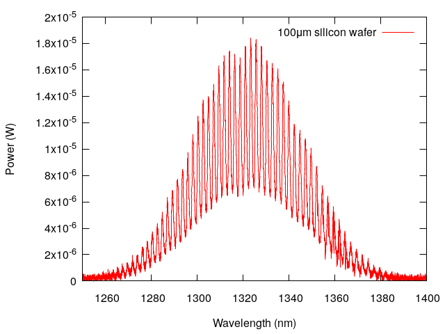
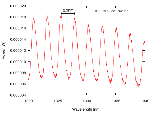
HR Coated Silicon Wafer
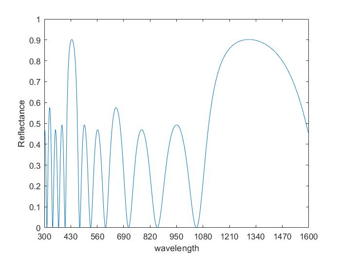
We wrote some MATLAB codes to simulate the performance of high reflection coating. Here, we are using a six-layer coating. The first layer from the air is the Si3N4, 163nm for thickness. After that, is the SiO2 layer, 226nm for thickness. Then the Si3N4 (163nm), SiO2 (226nm), Si3N4 (163nm), SiO2 (226nm).
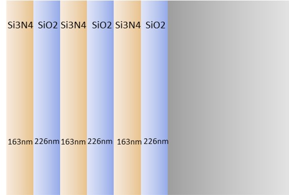 The reflective index of the coating should be as below:
Temperature Tuning of silicon etalon
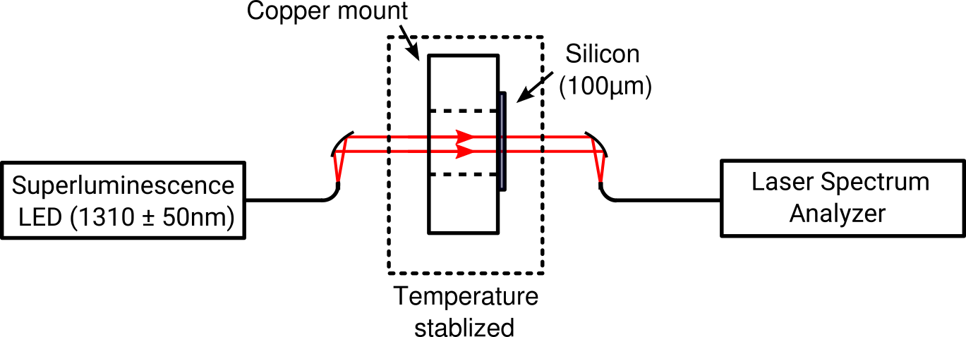
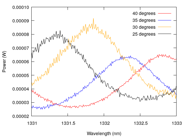
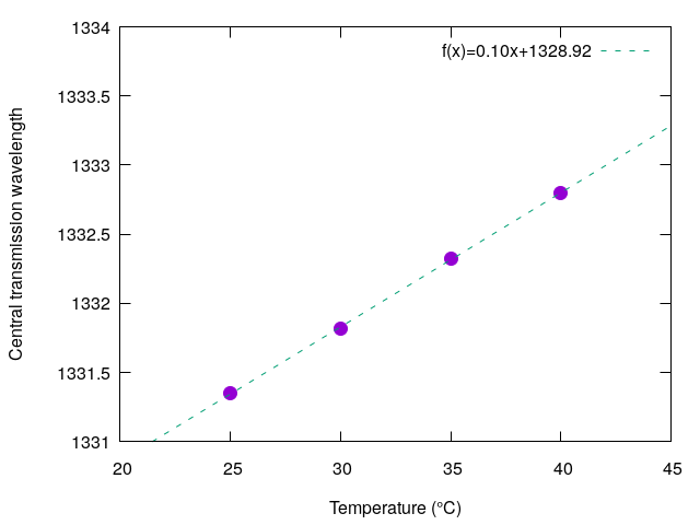
A small piece of the silicon wafer is mounted on a copper block with a 4mm diameter hole through hole. The copper serves as a thermally conductive mount for the silicon etalon and is placed on top of a Peltier stage. The temperature of this entire stack is adjusted and stabilized with a TEC controller. A few different temperatures were tried. Just to quickly note that the thermal expansion coefficient of silicon is ([1]).
Besides thermal expansion of the etalon, the refractive index of silicon also changes with varying temperature. One report of the thermal-optic coefficient of silicon can be found here([2]), which states a coefficient . Do note that the thermal-optical coefficient is two orders of magnitude larger than the thermal expansion coefficient, which suggest that the change in refractive index is the main contribution towards wavelength tuning of this etalon.
The shift of transmission center wavelength of a fringe can be expressed as: for 1310nm.


 The reflective index of the coating should be as below:


